Automated Temperature Regulation
Updated 3/8/2026
Automated Temperature Regulation
<big>Automated temperature regulation using logic chips</big>
Author: Jaffa
This logic will allow you to automatically keep your atmos temperature within a minimum and maximum temperature without annoying clicking. This setup assumes that your Wall Coolers and Wall Heaters are on a separate network for the room you want to control the temperature of. This also assumes your atmosphere isn't highly flammable. Network separation can be obtained through a Transformer or Area Power Controller.
Resources needed:
- 1 Gas Sensor
- 3 Kit (Logic I/O)
- 4 Kit (Logic Processor)
- 3 Kit (Logic Memory)
- At least 1 Wall Heater
- At least 1 Wall Cooler
- Many Cable coils
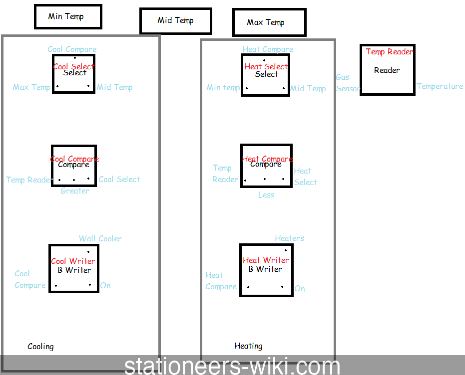
- The picture above shows all the Kit (Logic) components as well as their connections and also the components that make up the setup.* <big>Steps to placing the setup</big>
- Place the Gas Sensor in the middle of the room you want to control
- Place the Wall Heaters along a wall of the room
- Place the Wall Coolers along a wall of the room
- Place 1 Kit (Logic I/O) 'Logic Reader' variant
- Label the logic reader as "Temp Reader"
- Place 1 Kit (Logic Processor) 'Logic Select' variant for cooling Label this: "Cooling Select"
- Place 1 Kit (Logic Processor) 'Logic Compare' variant for cooling Label this: "Cooling Compare"
- Place 1 Kit (Logic I/O) 'Batch Writer' variant Label this: "Cooling Writer"
- Place 1 Kit (Logic Processor) 'Logic Select' variant Label this: "Heating Select"
- Place 1 Kit (Logic Processor) 'Logic Compare' variant Label this: "Heating Compare"
- Place 1 Kit (Logic I/O) 'Batch Writer' variant Label this: "Heating Writer"
- Place all 3 Kit (Logic Memory) units nearby Label these as "Min Temp", "Mid Temp " and "Max Temp" and set your desired temperatures in kelvin
- Wire all units together
- "Temp Reader" should be set to read "Temperature" from your Gas sensor (Note: Temperature from sensor is in Kelvin)
- Configure your "Cooling Select"; Select: "Cooling Compare" Input 1: "Max Temp" Input 2: "Mid Temp"
- Configure your "Cooling Compare"; Input 1: "Temp Reader" Mode: Greater Input 2: "Cooling Select"
- Configure your "Cooling Writer"; Input: "Cooling Compare" Output: Wall Cooler Setting: On
- Configure your "Heating Select"; Select: "Heating Compare" Input 1: "Min Temp" Input 2: "Mid Temp"
- Configure your "Heating Compare"; Input 1: "Temp Reader" Mode: Less Input 2: "Heating Select"
- Configure your "Heating Writer"; Input: "Heating Compare" Output: Wall Heater Setting: On
- Finally, turn on the logic chips in the following order: Logic Reader Select Unit Logic Compare Batch Writer